Adjusting the synchronization speed
When operating two syslog-ng Store Box (SSB) units in High Availability mode, every incoming data copied from the master (active) node to the slave (passive) node. Since synchronizing data can take up significant system-resources, the maximal speed of the synchronization is limited, by default, to 10 Mbps. However, this means that synchronizing large amount of data can take very long time, so it is useful to increase the synchronization speed in certain situations — for example, when synchronizing the disks after converting a single node to a high availability cluster.
The Basic Settings > High Availability > DRBD status field indicates whether the latest data (including SSB configuration, log files, and so on) is available on both SSB nodes. For a description of each possible status, see Understanding SSB cluster statuses.
To change the limit of the DRBD synchronization rate, navigate to Basic Settings > High Availability, select DRBD sync rate limit, and select the desired value.
Set the sync rate carefully. A high value is not recommended if the load of SSB is very high, as increasing the resources used by the synchronization process may degrade the general performance of SSB. On the other hand, the HA link's speed must exceed the speed of the incoming logs, else the web UI might become unresponsive and data loss can occur.
If you experience bursts of high activity, consider turning on asynchronous data replication.
Asynchronous data replication
When a high availability syslog-ng Store Box (SSB) cluster is operating in a high-latency environment or during brief periods of high load, there is a risk of slowness, latency or package loss. To manage this, you can compensate latency with asynchronous data replication.
Asynchronous data replication is a method where local write operations on the primary node are considered complete when the local disk write is finished and the replication packet is placed in the local TCP send buffer. It does not impact application performance, and tolerates network latency, allowing the use of physically distant storage nodes. However, because data is replicated at some point after local acknowledgement, the remote storage nodes are slightly out of step: if the local node at the primary data center breaks down, data loss occurs.
To turn asynchronous data replication on, navigate to Basic Settings > High Availability, and enable DRBD asynchronous mode. You have to reboot the cluster (click Reboot cluster) for the change to take effect.
Under prolonged heavy load, asynchronous data replication might not be able to compensate for latency or for high packet loss ratio (over 1%). In this situation, stopping the slave machine is recommended to avoid data loss at the temporary expense of redundancy.
Redundant heartbeat interfaces
To avoid unnecessary takeovers and to minimize the chance of split-brain situations, you can configure additional heartbeat interfaces in syslog-ng Store Box (SSB). These interfaces are used only to detect that the other node is still available, they are not used to synchronize data between the nodes (only heartbeat messages are transferred). For example, if the main HA interface breaks down, or is accidentally unplugged and the nodes can still access each other on the redundant HA interface, no takeover occurs, but no data is synchronized to the secondary node until the main HA link is restored. Similarly, if connection on the redundant heartbeat interface is lost, but the main HA connection is available, no takeover occurs.
If a redundant heartbeat interface is configured, its status is displayed in the Basic Settings > High Availability > Redundant Heartbeat status field, and also in the HA > Redundant field of the System monitor. For a description of each possible status, see Understanding SSB cluster statuses.
The redundant heartbeat interface is a virtual interface with a virtual MAC address that uses an existing interface of SSB (for example, the external or the management interface). The MAC address of the virtual redundant heartbeat interface is displayed as HA MAC.
The MAC address of the redundant heartbeat interface is generated in a way that it cannot interfere with the MAC addresses of physical interfaces. Similarly, the HA traffic on the redundant heartbeat interface cannot interfere with any other traffic on the interface used.
If the nodes lose connection on the main HA interface, and after a time the connection is lost on the redundant heartbeat interfaces as well, the secondary node becomes active. However, as the primary node was active for a time when no data synchronization was possible between the nodes, this results in a split-brain situation which must be resolved before the HA functionality can be restored. For details, see Recovering from a split brain situation.
NOTE: Even if redundant HA links are configured, if the dedicated HA link fails, the secondary node will not be visible on the Basic Settings > High Availability > High availability & Nodes page anymore.
SSB nodes use UDP port 694 to send each other heartbeat signals.
The following describes how to configure a redundant heartbeat interface.
To configure a redundant heartbeat interface
-
Navigate to Basic Settings > High Availability > Redundant heartbeat.
-
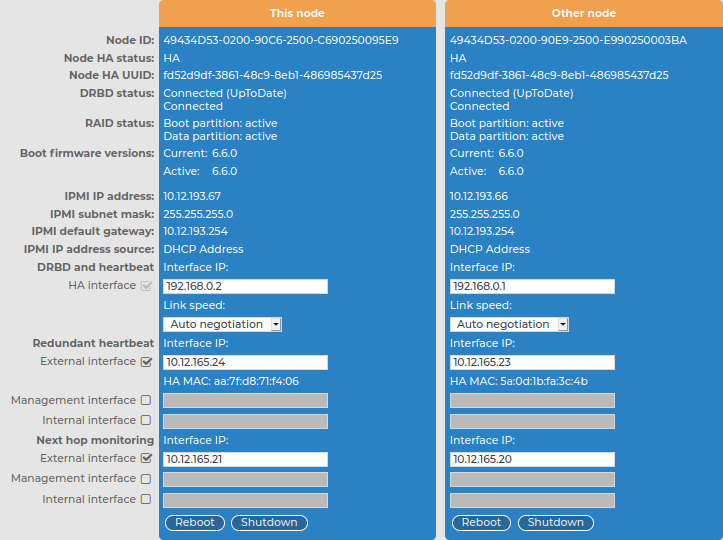
Enable the interface you want to use as redundant heartbeat interface (for example, External interface). Using an interface as a redundant heartbeat interface does not affect the original traffic of the interface.
Figure 71: Basic Settings > High Availability > Redundant heartbeat — Configuring redundant heartbeat interfaces
-
Enter an IP address into the This node > Redundant heartbeat > Interface IP field of the selected interface.
NOTE: Consider the following:
-
The two nodes must have different Interface IP.
-
If you do not use next hop monitoring on the redundant interface, you can use any Interface IP (even if otherwise it does not exist on that network).
-
If you use next hop monitoring on the redundant interface, the Interface IP address must be a real IP address that is visible from the other node.
-
If you use next hop monitoring on the redundant interface, the Interface IP must be accessible from the next-hop address, and vice-versa. For details on next hop monitoring, see Next-hop router monitoring.
-
Enter an IP address into the Other node > Redundant heartbeat > Interface IP field of the selected interface.
NOTE: Consider the following:
-
The two nodes must have different Interface IP.
-
If you do not use next hop monitoring on the redundant interface, you can use any Interface IP (even if otherwise it does not exist on that network).
-
If you use next hop monitoring on the redundant interface, the Interface IP address must be a real IP address that is visible from the other node.
-
If you use next hop monitoring on the redundant interface, the Interface IP must be accessible from the next-hop address, and vice-versa. For details on next hop monitoring, see Next-hop router monitoring.
-
Repeat the previous steps to add additional redundant heartbeat interfaces if needed.
-
Click  .
.
-
Restart the nodes for the changes to take effect: click Reboot Cluster.
Next-hop router monitoring
By default, HA takeover occurs only if the primary node (This node) stops working or becomes unreachable from the secondary node (Other node). However, this does not cover the scenario when the primary node becomes unaccessible to the outside world (for example its external interface or the router or switch connected to the external interface breaks down) while the secondary node would be still accessible (for example because it is connected to a different router).
To address such situations, you can specify IP addresses (usually next hop routers) to continuously monitor from both the primary and the secondary nodes using ICMP echo (ping) messages. One such address can be set up for every interface.
When setting up next hop monitoring, you have to make sure that the primary and secondary nodes can ping the specified address directly. You can either:
-
Choose the addresses of the redundant-HA syslog-ng Store Box (SSB) interfaces so that they are on the same subnet as the next-hop address
-
Configure the next-hop device with an additional IP-address that is on the same subnet as the redundant-HA SSB interfaces facing it
If any of the monitored addresses becomes unreachable from the primary node while being reachable from the secondary node (in other words, more monitored addresses are accessible from the secondary node), then it is assumed that the primary node is unreachable and a forced takeover occurs — even if the primary node is otherwise functional.
Naturally, if the secondary node is not capable of taking over the primary node (for example, because there is data not yet synchronized from the current primary node), no takeover is performed.
The following describes how to configure next hop monitoring.
To configure next hop monitoring
-
Navigate to Basic Settings > High Availability > Next hop monitoring.
-
Select the interface to use for monitoring its next-hop router.
Figure 72: Basic Settings > High Availability > Next hop monitoring — Configuring next hop monitoring
-
Enter the IP address to monitor from the current primary node (for example, the IP address of the router or the switch connected to the interface) into the This node > Next hop monitoring > Interface IP field of the selected interface. This IP address must be a real IP address that is visible from the interface, and must be on the same local network segment.
-
Enter the IP address to monitor from the current secondary node (for example, the IP address of the router or the switch connected to the interface) into the Other node > Next hop monitoring > Interface IP field of the selected interface. This IP address must be a real IP address that is visible from the interface, and must be on the same local network segment.
-
Repeat the previous steps to add IP addresses to be monitored from the other interfaces if needed.
-
Click .
|

|
Caution:
For the changes to take effect, you have to restart both nodes. To restart both nodes, click Reboot Cluster. |
