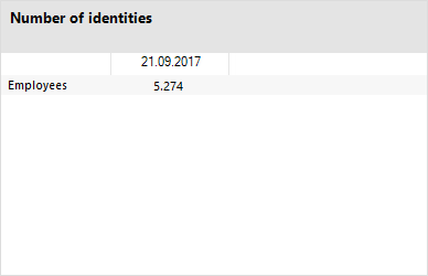
In order to visualize statistics in the One Identity Manager administration tools, such as the Manager, you have to link the statistics into the user interface as a custom menu item.
You will typically find statistics in the Manager under the Info System navigation item in nearly any category. You should set up custom menu items for statistics under an info system like this. All statistics that are defined at one menu level are displayed on one form.
You can show reports that you create in the Report Editor or in the Manager in the statistics. In the Manager's info system, the report opens when you double-click on the statistics header.
Statistics can also be linked as form elements into overview forms. To do this, use the Overview Form Editor.
NOTE: If you set up a custom info system, ensure that the menu item under which you define the statistics, is labeled with Not expandable by user and Force open menu item.
For more information about general properties of menu items, see Menu item properties. Take note of the following properties for menu items.
Table 119: Statistics properties
|
Entry type |
Select the entry type Statistics. |
|
Caption |
The caption given here, overwrites the statistic definition caption. Leave this field empty if you want to use the statistic definition display name. |
|
Statistics |
Enter the statistic definition to be displayed. |
|
Diagram type |
Select the diagram type that is going to represent the statistic.
|
|
Alignment |
Positioning of statistics on the overview form. This layout information is used if the statistic is used as a form element on an overview form. |
|
Background |
Background color of the form elements on the overview form. This layout information is used if the statistic is used as a form element on an overview form. |
All menu items that are to be displayed in an application user interface have to be assigned to a permissions group and an application.
In the Manager's info system, you can display reports that you create in the Report Editor as statistics. To do this, you must alter the user interface of the Manager program. The report opens when you double-click on the statistic's header.
To display a report as a statistic
-
In the Designer, create a user interface form.
-
In the Designer, select the User interface > Forms > User interface forms category.
-
Select the Edit form task.
-
Select the Form > Insert menu item.
-
Edit the interface form's main data.
Take the following cases into account:
-
Use the VI_Report form definition
This form definition is configured to display in the graphical user interface and web applications. You only need to set up one interface form for this. Which form template will be used to display the interface form is decided dynamically, depending on usage.
-
In the form's configuration data, pass the name of the report to run (DialogReport.ReportName) in the Properties section.
Syntax:
<DialogSheetDefinition FormatVersion="1.0">
<Properties>
<Property Name="ReportName">ReportName from the DialogReport</Property> table
</Properties>
</DialogSheetDefinition>
-
Assign the user interface form to the applications and permissions groups.
-
In the Designer, create a menu item.
-
In the Designer, select User interface > User interface navigation category.
-
In the User Interface Editor, select the menu item for the statistics item to show the report.
-
Select New.
-
Edit the main data of the menu item.
-
Assign the menu item to the Manager application and permissions groups.
-
Assign the user interface form to the menu item.
-
Select the Database > Save to database and click Save.
Simple reports that you create in the Manager can be displayed as statistics in the Manager's info system. To do this, in the Designer, you must alter the user interface of the Manager program. In the Manager's info system, the report opens when you double-click on the statistic's header.
For more information about how to create reports in the Manager, see the One Identity Manager Report Subscriptions Administration Guide and the One Identity Manager Operational Guide.
To display a simple report in the statistics
-
In the Designer, create a user interface form.
-
In the Designer, select the User interface > Forms > User interface forms category.
-
Select the Edit form task.
-
Select the Form > Insert menu item.
-
Edit the interface form's main data.
Take the following cases into account:
-
Use the VI_Report form definition.
This form definition is configured to display in the graphical user interface and web applications. You only need to set up one interface form for this. Which form template will be used to display the interface form is decided dynamically, depending on usage.
-
In the form’s configuration data, enter the UID of the simple report (RPSReport.UID_RPSReport) in the Properties section.
Syntax:
<DialogSheetDefinition FormatVersion="1.0">
<Properties>
<Property name="UIDRPSReport">UID_RPSReport from the RPSReport</Property> table
</Properties>
</DialogSheetDefinition>
-
Assign the user interface form to the Manager program and the permissions groups.
-
In the Designer, create a menu item.
-
In the Designer, select User interface > User interface navigation category.
-
In the User Interface Editor, select the menu item for the statistics item to show the report.
-
Select New.
-
Edit the main data of the menu item.
-
Assign the menu item to the Manager application and permissions groups.
-
Assign the user interface form to the menu item.
-
Select the Database > Save to database and click Save.
There are several diagram types available for visualizing statistics.
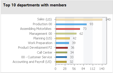
Bar chart
A bar chart can be used to visualize comparisons between measurements. The actual measurement of the ElementValue column and the identifier for ElementName column are used to label the diagram.
Figure 23: Bar chart example
Pie chart
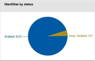
A pie chart can be used to visualize the measurements as a percentage of the base measurement. The actual measurement of the ElementValue column and the identifier for ElementName column are used to label the diagram.
Figure 24: Pie chart example
Line diagram
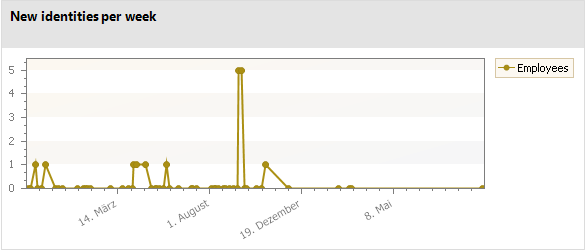
A line diagram can be used to visualize a data sequence over a specified time period. The time axis is scaled in proportion to the time scale given in the statistic definition. The number of measurements in the line diagram results from measurement runs that are entered in the statistic definition from the history data. Click with the mouse on a point of measurement and a tooltip showing the measurement is displayed.
Figure 25: Line diagram example
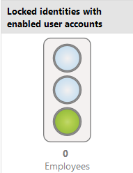
Traffic light
A traffic light diagram can be used to visualize the state of the system. The state is indicated by the color. The threshold factors given in the statistic definition determine when which status is reached.
Table 120: Meaning of the colors
|
Green |
correct |
|
Yellow |
acceptable |
|
Red |
unacceptable |
The actual measurement of the ElementValue column and the identifier for ElementName column are used to label the diagram.
Figure 26: Traffic light example
Tachometer
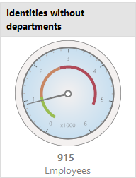
A tachometer diagram can be used to visualize the state of the system in more detail than in a traffic light diagram. The base measurement is also displayed. The state is indicated by the color. The threshold factors given in the statistic definition determine when which status is reached. The actual measurement of the ElementValue column and the identifier for ElementName column are used to label the diagram.
Figure 27: Tachometer diagram example
Thermometer
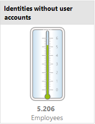
A thermometer diagram can be used to visualize the state of the system in more detail that in a traffic light diagram. The state is indicated by a color scale on the side of the diagram. The threshold factors given in the statistic definition determine when which status is reached. The actual measurement of the ElementValue column and the identifier for ElementName column are used to label the diagram.
Figure 28: Thermometer diagram example
Table
This diagram type can be used to visualize the measurements in table form. Enter a number of archived measurements runs in the statistic definition, to present the data over a specified time period.
Figure 29: Table example
