HA cluster configuration and management options
This section is about the available configuration and management options for HA clusters.
Setting up a high availability cluster
For detailed instructions about setting up a HA cluster, see "Installing two SPS units in HA mode" in the Installation Guide.
Adjust the DRBD (primary-secondary) synchronization speed
You can change the limit of the DRBD synchronization rate. Note that this does not change the speed of normal data replication. For details, see Adjusting the synchronization speed.
Configure redundant heartbeat interfaces
You can configure virtual interfaces for each HA node to monitor the availability of the other node. For details, see Redundant heartbeat interfaces.
Configure next-hop monitoring
You can provide IP addresses (usually next hop routers) to continuously monitor both the primary node and the secondary node by using ICMP echo (ping) messages. If any of the monitored addresses becomes unreachable from the primary node while being reachable from the secondary node (in other words, more monitored addresses are accessible from the secondary node), then it is assumed that the primary node is unreachable and a forced takeover occurs – even if the primary node is otherwise functional. For details, see Next-hop router monitoring.
Reboot the HA cluster
To reboot both nodes, click Reboot Cluster. To prevent takeover, a token is placed on the secondary node. While this token persists, the secondary node halts its boot process to make sure that the primary node boots first. Following reboot, the primary node removes this token from the secondary node, allowing it to continue with the boot process.
If the token still persists on the secondary node following reboot, the Unblock Slave Node button is displayed. Clicking the button removes the token, and reboots the secondary node.
Reboot a node
This option reboots the selected node.
When rebooting the nodes of a cluster, reboot the other node (that is, the secondary node) first to avoid unnecessary takeovers.
Shutdown a node
This option forces the selected node to shut down.
When shutting down the nodes of a cluster, shut down the other node (that is, the secondary node) first. When powering on the nodes, start the primary node first to avoid unnecessary takeovers.
Manual takeover
To activate the other node (that is, the secondary node) and disable the currently active node, click Activate slave.
Activating the secondary node terminates all connections of One Identity Safeguard for Privileged Sessions (SPS) and might result in data loss. The secondary node becomes active after about 60 seconds, during which the protected servers cannot be accessed.
Adjusting the synchronization speed
One Identity Safeguard for Privileged Sessions (SPS) synchronizes the content of the hard disk of the primary node (previously also referred to as master node) and the secondary node (previously also referred to as slave node) in the following cases.
-
When you configure two SPS units to operate in High Availability mode (converting a single node to a high availability cluster),
-
when you replace a node from a cluster, or
-
when recovering from a split-brain situation.
-
Normal data replication (copying incoming data, for example, audit trails from the primary node to the secondary node is not synchronization.
Since this synchronization can take up significant system-resources, the maximal speed of the synchronization is limited, by default, to 10 Mbps. However, this means that synchronizing large amount of data can take very long time, so it is useful to increase the synchronization speed in certain situations —.
To change the limit of the DRBD synchronization rate, navigate to Basic Settings > High Availability > DRBD sync rate limit, and select the desired value. Note the following points before changing the DRBD sync rate limit option.
-
The Basic Settings > High Availability > DRBD sync rate limit option is visible only when synchronization is in progress, or when you have clicked Convert to Cluster but have not rebooted the cluster yet.
-
Changing this option does not change the limit of the data replication speed.
-
Set the sync rate carefully. A high value is not recommended if the load of SPS is very high, as increasing the resources used by the synchronization process may degrade the general performance of SPS. On the other hand, the HA link's speed must exceed the speed of the incoming data, else the web UI might become unresponsive and data loss can occur.
The Basic Settings > High Availability > DRBD status field indicates whether the latest data (including SPS configuration,
Redundant heartbeat interfaces
To avoid unnecessary takeovers and to minimize the chance of split-brain situations, you can configure additional heartbeat interfaces in One Identity Safeguard for Privileged Sessions (SPS). These interfaces are used only to detect that the other node is still available, they are not used to synchronize data between the nodes (only heartbeat messages are transferred). For example, if the main HA interface breaks down, or is accidentally unplugged and the nodes can still access each other on the redundant HA interface, no takeover occurs, but no data is synchronized to the secondary node until the main HA link is restored. Similarly, if connection on the redundant heartbeat interface is lost, but the main HA connection is available, no takeover occurs.
If a redundant heartbeat interface is configured, its status is displayed in the Basic Settings > High Availability > Redundant Heartbeat status field, and also in the HA > Redundant field of the System monitor. For a description of each possible status, see Understanding One Identity Safeguard for Privileged Sessions (SPS) cluster statuses.
The redundant heartbeat interface is a virtual interface with a virtual MAC address that uses an existing interface of SPS. The MAC address of the virtual redundant heartbeat interface is displayed as HA MAC. The MAC address of the redundant heartbeat interface is generated in a way that it cannot interfere with the MAC addresses of physical interfaces. Similarly, the HA traffic on the redundant heartbeat interface cannot interfere with any other traffic on the interface used.
If the nodes lose connection on the main HA interface, and after a time the connection is lost on the redundant heartbeat interfaces as well, the secondary node becomes active. However, as the primary node was active for a time when no data synchronization was possible between the nodes, this results in a split-brain situation, which must be resolved before the HA functionality can be restored. For details, see Recovering from a split brain situation.
|
|
NOTE:
Even if redundant HA links are configured, if the dedicated HA link fails, the secondary node will not be visible on the High Availability page anymore. |

SPS nodes use UDP port 694 to send each other heartbeat signals.
To configure a redundant heartbeat interface
-
Navigate to Basic Settings > High Availability > Interfaces for Heartbeat.
-
Select the interface you want to use as redundant heartbeat interface (for example Physical interface 1). Using an interface as a redundant heartbeat interface does not affect the original traffic of the interface.
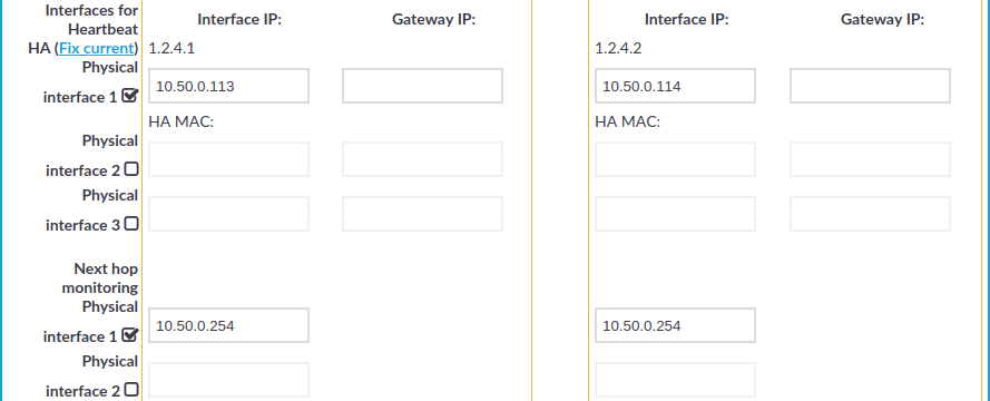
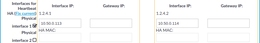
Figure 100: Basic Settings > High Availability — Configuring redundant heartbeat interfaces
-
Enter an IP address into the This node > Interface IP field of the selected interface. Note the following:
-
The two nodes must have different Interface IP.
-
If you do not use next hop monitoring on the redundant interface, you can use any Interface IP (even if otherwise it does not exist on that network).
-
If you use next hop monitoring on the redundant interface, the Interface IP address must be a real IP address that is visible from the other node.
-
If you use next hop monitoring on the redundant interface, the Interface IP must be accessible from the next-hop address, and vice-versa. For details on next hop monitoring, see Next-hop router monitoring.
Use an IPv4 address.
-
-
If the two nodes are in a different subnetwork, enter the IP address of the local gateway into the This node > Gateway IP field. The Interface IP address of the node must be accessible from the Gateway IP address.
Use an IPv4 address.
-
Enter an IP address into the Other node > Interface IP field of the selected interface. Note the following:
-
The two nodes must have different Interface IP.
-
If you do not use next hop monitoring on the redundant interface, you can use any Interface IP (even if otherwise it does not exist on that network).
-
If you use next hop monitoring on the redundant interface, the Interface IP address must be a real IP address that is visible from the other node.
-
If you use next hop monitoring on the redundant interface, the Interface IP must be accessible from the next-hop address, and vice-versa. For details on next hop monitoring, see Next-hop router monitoring.
Use an IPv4 address.
-
-
If the two nodes are in a different subnetwork, enter the IP address of the local gateway into the Other node > Gateway IP field. The Interface IP address of the node must be accessible from the Gateway IP address.
Use an IPv4 address.
-
Repeat the previous steps to add additional redundant heartbeat interfaces if needed.
-
Click
.
-
Restart the nodes for the changes to take effect: click Reboot Cluster.
Next-hop router monitoring
By default, HA takeover occurs only if the primary node stops working or becomes unreachable from the secondary node. However, this does not cover the scenario when the primary node becomes unaccessible to the outside world while the secondary node would be still accessible (for example because it is connected to a different router).
To address such situations, you can specify IP addresses (usually next hop routers) to continuously monitor both the primary node and the secondary node by using ICMP echo (ping) messages. One such address can be set up for every interface.
When setting up next hop monitoring, you have to make sure that the secondary and secondary nodes can ping the specified address directly. You can either:
-
Choose the addresses of the redundant-HA One Identity Safeguard for Privileged Sessions (SPS) interfaces so that they are on the same subnet as the next-hop address
-
Configure the next-hop device with an additional IP-address that is on the same subnet as the redundant-HA SPS interfaces facing it
If any of the monitored addresses becomes unreachable from the primary node while being reachable from the secondary node (in other words, more monitored addresses are accessible from the secondary node) then it is assumed that the primary node is unreachable and a forced takeover occurs — even if the primary node is otherwise functional.
Naturally, if the secondary node is not capable of taking over the primary node (for example, because there is data not yet synchronized from the current primary node), no takeover is performed.
To configure next hop monitoring
-
Navigate to Basic Settings > High Availability > Next hop monitoring.
-
Select the interface to use for monitoring its next-hop router.
Figure 101: Basic Settings > High Availability — Configuring next hop monitoring
-
Enter the IP address to monitor from the current primary node (for example, the IP address of the router or the switch connected to the interface) into the This node > Next hop IP field of the selected interface. This IP address must be a real IP address that is visible from the interface, and must be on the same local network segment.
Use an IPv4 address.
-
Enter the IP address to monitor from the current secondary node (for example the IP address of the router or the switch connected to the interface) into the Other node > Next hop IP field of the selected interface. This IP address must be a real IP address that is visible from the interface, and must be on the same local network segment.
Use an IPv4 address.
-
Repeat the previous steps to add IP addresses to be monitored from the other interfaces if needed.
-
Click
Caution: For the changes to take effect, you have to restart both nodes. To restart both nodes, click Reboot Cluster.